
H. Rahman2023-07-04T18:12:04+06:00
Binary Counter
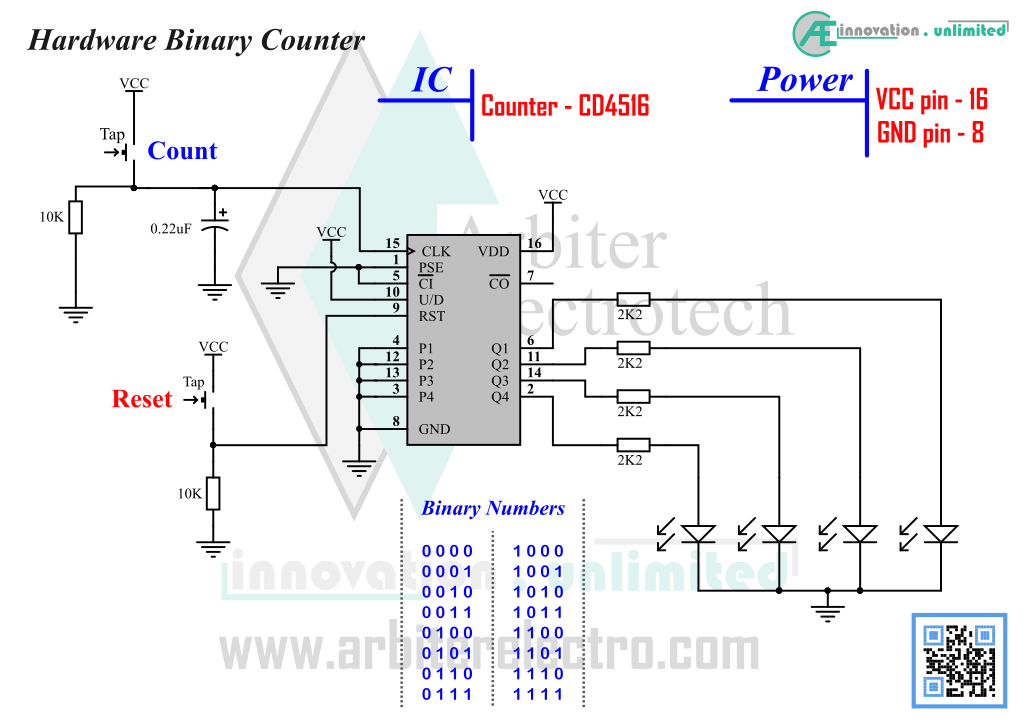
Counters are a vital part of digital electronics. Experiment 3 demonstrates the very basic principle of hardware binary counter. In the experiment, we will build a binary counter circuit using a dedicated binary counter IC. This IC is a dedicated 4-bit binary Up/Down counter i.e. the counter can count in both Upward or Downward. A 4-bit counter can count from binary 0000 to 1111 in binary (0 to 15 in decimal). These dedicated chips are designed for the sole purpose of counting. These counters can count either UP or DOWN and resets itself to zero if/when they reach the counting limit (conditional and manual reset will require extra circuitry). Counters are an essential part of manufacturing industry. They are essential for keeping count in real life scenario such as pharmaceuticals industry where they are used to count the number of pills going in to a bottle. We are going to look at a very widely used counter IC which has been in the market for at least 30 years.
Components:
1. One CD4516 IC (binary Up/Down counter)
2. Two push switch
3. Four 2.2KΩ Resistor, Two 10KΩ Resistor
4. One 220nf Capacitor (has 0.22µF written on it)
5. Four LED (any color)
Steps:
1. Set up the circuit in the schematic above.
2. Press Reset button (button connected to pin 9 of the IC) to reset the counter to zero. All LED should be off.
3. Press count button (button connected to pin 15 of the IC) once to increment count by one. Notice the output LED change its state. Press count a few times and see the LED change.
4. Press Reset and zero out the counter. Now press count button once for one increment and compare it to table. Check if the LED are following the counter sequence shown in the table.
5. If everything is set up properly, the LED should be following the sequence of binary counter ( 0000 to 1111 ).
Explanation:
What happens is that every time there is a positive edge on the CLK input of the counter IC, the counter counts +1. The direction of count depends on the IC pin10. This pin determines if the counter counts up or down. This experiment has pin 10 set to VCC and therefore the count is upward (starting from 0 and count +1 for each clk signal). The output is 4-bit binary which means the counter can count from 0 to 15 (24 -1 = 15). If the count goes beyond 15, it will by itself reset to 0. If count goes beyond zero (down counter), the count automatically becomes 15. This process of resetting to 0 or 15 after maximum limit is reached is called “Overflow”.
Leave a Reply