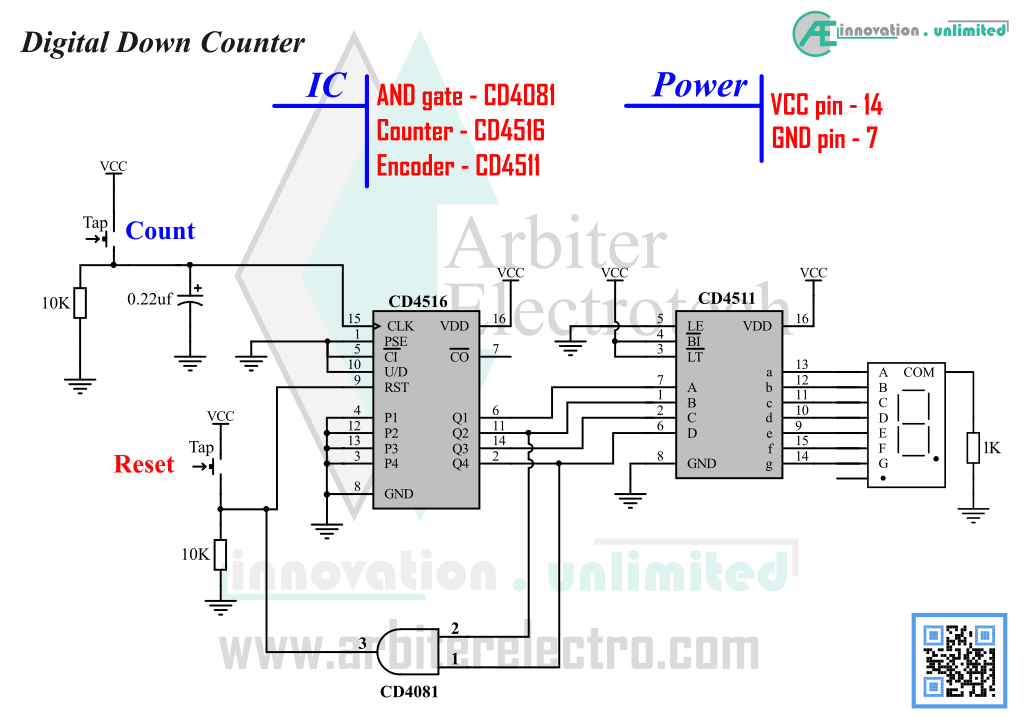
This experiment will use the same circuit used before in the Experiment – 6 with a slight modification. A digital counter can count in both upward and downward direction. Up counter starts counting from 0 and goes like 0, 1, 2, 3, 4, 5 etc. A Down counter starts from 15 (for this IC, 15 is the highest limit for a 4-bit counter) and goes like 15, 14, 13, 12 etc. all the way down to 0. The counter IC we have been using (CD4516) can count in both Up and Down direction. There is a pin on the IC that determines which way the counter is going to count. Setting that pin to HIGH or LOW determines the counter direction. This experiment demonstrates how to do it. The modification is to set the down count pin (pin 10) of the IC to GND. To count up, the pin is connected/pulled up to VCC.
Steps:
1. Power down the circuit if it is not already powered down.
2. Set pin 10 (named U/D) to LOW (connect the pin to GND to set it to LOW).
3. Power up the circuit and reset the IC.
4. Press count button to start counting down. The display should go from 0 to blank.
5. Keep counting until the display shows 9.
6. After 9, more count should show 8, 7, 6 etc all the way to 0.
This time the counter is counting downward. The counter starts from 0. As the counter is counting downward, it overflows to 15 after 0. The display goes blank after 0 is because the 4511 cannot display 15 or any double digit decimal number. That’s why the count needs to decrease to 9 before we can see anything on the display.

Leave a Reply