The best way to learn electronics is by trying it yourself. The following experiments will show you the basics of logic gates. In the experiment below, we are going to demonstrate the characteristics of the most basic logic gate, The Not Gate.
To work with digital circuits, the user must provide input signals. The input signals are often referred to as Stimulus. The input signals or Stimulus can be generated with the following circuits.
Experiment 1 is the first experiment of this literature. This experiment will demonstrate the basic working principle of digital logic. However, before starting experiments with the logic gates, it is important to know some basic and fundamental concepts relating to hardware. An engineer must know how to power the DUT/SUT, how to apply test signals on the DUT/SUT and the meaning of the output signals. For your information, DUT means “Device Under Test “and SUT means “System Under Test”.
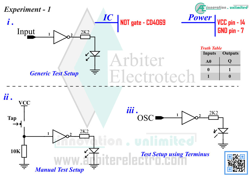
We will start with the simplest logic gate, The NOT gate or Inverter.. NOT gates have one input and one output. The output is always inverse or 2’s compliment of the input. Schematic of the circuit is shown below. Note that there are three circuits with only difference on the input. The circuit (i) shows how NOT gate is connected without any input circuit. The circuit (ii) shows the convenient method of testing by connecting a button. Circuit (iii) makes use of the Terminus.
Components:
1. One CD4069 IC (NOT gate) 2.One 10KΩ Resistor 3.One 2.2KΩ Resistor 4.One LED (any color) 5. One tap switch
Steps:
1. Set up the circuit No (ii) using schematic above. The schematic shows a single gate connected to GND via a resistor. From the NOT gate pinout seen earlier, it is seen that the input of the NOT gate is at Pin 1 and output is at Pin 2. So, the LED is connected to Pin 2 via the resistor and the input signal goes to the Pin 1 via the 10KΩ resistor.
2. Connect the Terminus power to the breadboard power rails
3. Currently, it is connected to GND via a 10K resistor, and therefore, the NOT gate input is LOW and the output LED is glowing.
4. Push the tap switch to feed the input side a digital HIGH by connecting it to VCC. Observe the LED. The LED should stop glowing.
5. Next, release the switch and feed the input side a digital LOW by connecting it to GND and observe the LED. The LED should be glowing.
Explanation
To explain what happened in the experiment, we need to use the truth table (see the schematic). We are using a NOT gate. Now see the steps that we have just used in the experiment. Notice that, we started off the experiment with the input of the NOT gate connected to the GND rail. The voltage of ground rail (GND) is zero volts (0v). 0 volts meets the standard set for logic LOW. As the input of the NOT gate is logic LOW, the output is inverted i.e. output is HIGH. For logic LOW, there should be approximately 0 volts on the output of the gate and so the LED doesn’t glow.
Next we connected the input of the NOT gate to positive voltage rail (VCC). The voltage of the ground voltage rail is approx. +5v. Voltage equal or greater than 2.4v meets the requirement for logic HIGH. Again, for input of logic HIGH, the output is inverted to logic LOW. For logic LOW, there is approx. 5 volts on the output of the gate and so the LED starts glowing.
Connecting a LED to the output of the logic gate is a great way to determine the output state. However, there is a drawback to this technique. If the digital signal is LOW, the LED stays OFF, and the LED is ON if the digital state is HIGH. But if the input is at metastable state, the LED maybe ON, which is false positive. A LED will light up as long as the input voltage is greater than its forward voltage. Therefore, LED lights up for both digital HIGH and metastable state. To determine the digital state properly, a Logic Probe is used (schematic is given on the DIY Projects chapter).