
H. Rahman2026-05-13T17:46:07+06:00
Reset Logic
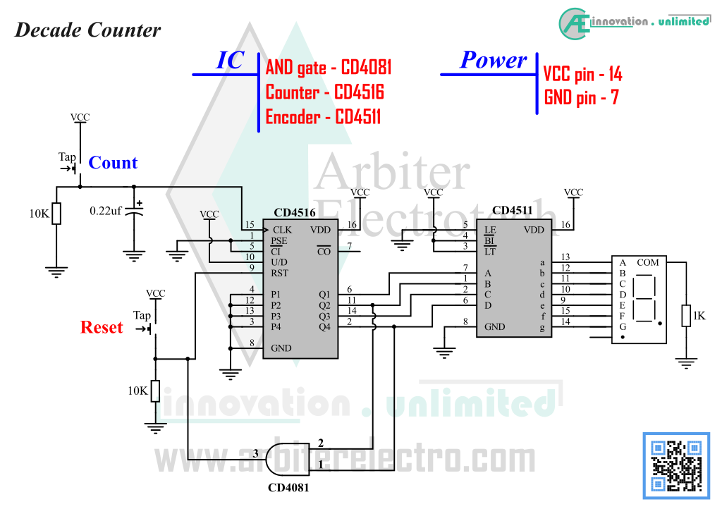
We have built a counter in Experiment – 5 that can show the count in decimal on a display. However, the circuit is not very practical as the display blanks out after it reaches 9. In this experiment, we will fix that problem and make the counter reset to 0 if it reaches a value greater than 9. The digital counter has a reset pin that can be used to reset the count of the counter. We will define a reset logic to reset the counter in a controlled manner to suit our requirements. We will have to modify the circuit used in Experiment – 5 a little bit to do just that. The modification is to add an AND gate to the circuit. The AND gate is used to define a reset logic for the digital counter. The complete schematic is given below. Construct the circuit and follow the steps.
Components:
1. One CD4081 IC (AND gate)
2. One CD4516 IC (binary Up/Down counter)
3. Two push switch
4. Four 2.2KΩ Resistor, Two 10KΩ Resistor
5. One 220nf Capacitor (has 0.22µF written on it)
6. Four LED (any color)
Steps:
1. Modify the counter circuit to connect the AND gate as shown in the schematic
2. Power ON the circuit and reset it
3. Push count button to increase count until you reach 9 (binary 1001)
4. If the circuit is properly assembled, after 9, the IC should show 0 (all LED is OFF)
So, what happened you may ask?? Remember in an earlier we have explained how CD4011 can only show digits from 0 to 9 and any binary input not within decimal 0 to 9 is discarded. In this experiment we tried to make sure that when the counter moves from decimal 9 to decimal 10, instead of blanking out, the display will show 0. The only way to ensure that the display is showing 0 is by making sure that the inputs of CD4011 is at binary 0. For that, we need to make all the output of the counter CD4516 LOW. On the other hand, the counter can count up to decimal 15 (binary 1111). So we need to make sure that the counter can’t count beyond 9. We did that by using the AND gate. If you look at the schematic, you will see that that the output of the AND gate is connected to the Reset pin of the counter. The input of the AND gate is connected to the two output of the counter. The exact procedure is explained below. When the counter reaches decimal 10, the AND gate output is HIGH and that makes the Reset pin of the counter HIGH. Thus the counter is reset to 0. In the circuit, we are forcing the counter to reset to 0 if the count exceeds 9 (more specifically, the counter reset if it is at decimal 10). Reset logic can be used to make the CD4516 to count in binary, octal, decimal & in hexadecimal. The reader can try to modify the reset logic to convert the decade counter to binary or octal. (Hint, reset at 8 for octal, reset at 2 for binary.)