
H. Rahman2026-05-13T17:46:07+06:00
Introduction
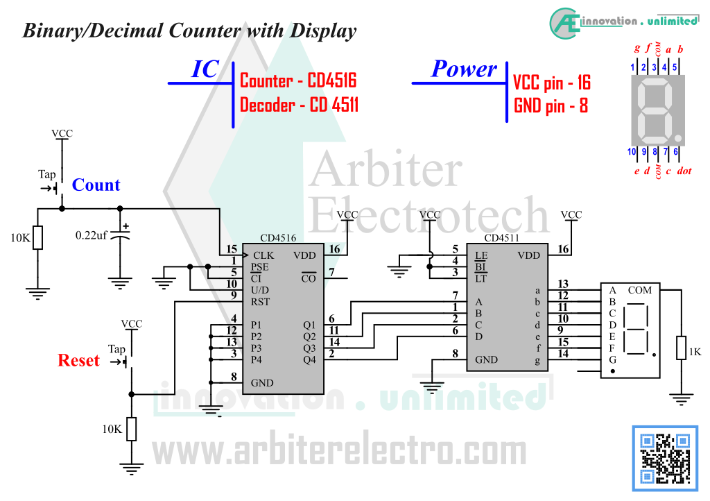
This experiment introduces an IC that can be used to convert binary number to its corresponding decimal number and display it on a seven segment display. The CD4511 is a dedicated Binary/BCD to Seven Segment Converter IC. This practical hardware counter can convert a binary number and show it on a seven segment display. A seven segment display is a type of display that can be used to display number and a few alphabets. It is a very simple type of display that uses LED, arranged in a specific way, to display number and alphabets. As the display uses LED, it can be read and seen in the dark. One of the most widely used display in the electronics design industry is a seven segment display. By using the IC (CD4511) discussed in this experiment, the design engineers can easily convert a 4-bit binary number to its corresponding decimal value and display it. This experiment demonstrates how to use CD4511 and a 7 segment display to convert binary number into decimal number. The complete schematic is given below. The circuit is the hardware binary counter with additional components.
Components:
1. One CD4511 IC (Binary to BCD Decoder)
2. One CD4516 IC (Binary Up/Down counter)
3. Two tap switch
4. One 7 segment display
5. Two 10KΩ Resistors, One 2.2KΩ Resistors
6. One 0.22µf capacitor
Steps:
1. Assemble the circuit as in the schematic above
2. Power up the circuit.
3. Press Reset on the counter. The 7 segment display should show 0.
4. Press the count button to increment the count. The seven segment display should show decimal number 1.
5. Reset the counter and start from 0. See if the display is showing numbers in proper sequence i.e. 1, 2, 3, 4 etc..
The IC counts only when there is a LOW to HIGH transition on its CLK input pin. Every time the signal level transits from 0 to 1, the IC counts +1, i.e. it adds 1 to its present count. To count, we need to press the tap switch. When tap switch is released, it is the switch literally becomes an open circuit. The 10KΩ resistor connects the CLK input to GND (logic 0). When the tap switch is pressed, the switch shorts the CLK input to VCC (logic 1). Thus we have a logic 0 to 1 or LOW to HIGH transition. This causes the CD4516 counter IC to count +1. When the tap switch is released, the switch opens and the CLK is now connected to GND or logic 0. The capacitor prevents the contact bouncing as explained earlier. The seven segment display and the IC CD4011 was also explained earlier.
Notice that after you reach 9, the display turns off. The reason why the display is turned off is because the CD4511 IC cannot show any number greater than 9. More specifically, CD4511 responds only to binary combinations (binary numbers) that converts to a single digit decimal number. Therefore, CD4511 can display only single digit numbers. All decimal numbers greater than 9 have more than 1 digit and to CD4511, those numbers are over the range. So the IC shows nothing on the display.