H. Rahman2026-05-13T17:46:07+06:00
Experiment - 4
Experiment 4 uses the same circuit that was used in experiment 3. So you don’t need to set up a new circuit. This experiment is designed to show you a very troubling phenomenon of digital electronics. Novice of digital electronics, college level engineering students and occasionally veterans may get in trouble with it. The cause of this problem is so simple that it is very easy to miss. The phenomenon is annoying to say the least. The phenomenon is called “Contact Bouncing”. We are going to acquaint you to this phenomenon by an experiment and show you how to fix it and/or how to avoid it. We will be using the same circuit of the Experiment -3. A small modification to the circuit is required for the experiment.
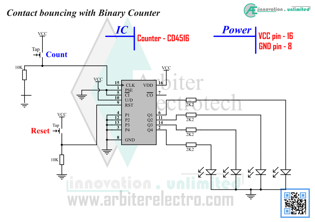
Steps:
1. We are using the same circuit used in experiment 3. Assemble the circuit (if it is not already assembled and is in working condition).
2. If the circuit is powered, power down the circuit by disconnecting VCC. We are going to make a very small modification to the circuit.
3. The modification of the circuit is to remove the 0.22µF capacitor from the clock input circuit. Schematic above shows the circuit in its modified form.
4. After the modification, power ON the circuit.
5. Press the Reset button to zero out the count. After the counter has been zeroed out, we are ready to proceed.
6. Press the count button one time only and observe the output. The output should be showing only LSB LED to be active. But it is highly likely that your output is something else.
7. Press count button a few more times and each time, compare the output to binary sequence. It is highly likely that the counter will not follow the sequence perfectly.
8. Now power down the circuit and add the capacitor as before.
9. Power ON the circuit and reset it. Press count button once only. The output should be a single binary count.
Explanation:
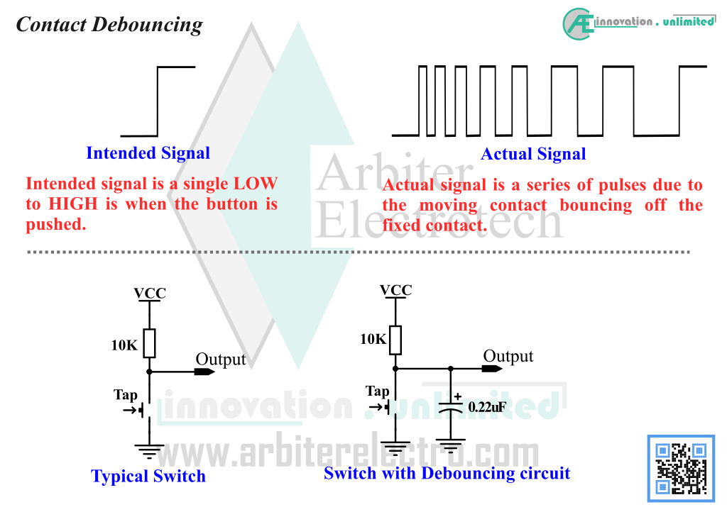
So, what happened you ask?? Answer is simple. What happens when you drop a ball on the floor from some height? The ball hits the floor, bounces up, goes down again, bounces up again and so on. The ball settles to the ground after bouncing off the floor a few times. The same thing happens with mechanical switches. The tap switch, used to increment the count of the counter, is a mechanical switch. It has two sets of contact. One set is fixed to the switch’s base. The other set is attached to the moving part (the part that you push) of the switch. Electrical connection is made by pushing the moving set of conductor to the fixed set of conductor. When you push the moving portion to make an electrical connection, the moving conductor hits the fixed conductor and bounces up and down the fixed conductor just like the ball dropped on the floor. This bouncing of the conductor causes the switch to make and break contact a few times before it gets settled in and makes a solid contact. However, to the digital circuit, the make and break connection is equivalent to several individual signals. The counter thinks it is getting several input signals and reacts likewise when in reality, it is getting only one count signal. So, the counter shows a larger count than what’s there in reality. This phenomenon is called “Contact Bouncing”.
To fix this problem, we add a small capacitor on the count signal pin. A capacitor can store electrical charges. When the voltage on the count pin fluctuates due to switch bouncing, the capacitor prevents the count pin from fluctuating by discharging its stored energy and prevents the counter from getting the false signals. This process of adding a capacitor to prevent switch bouncing is called “Debouncing”. Any electronic equipment that uses mechanical switch, must have a debouncing circuit. That means everyday electronic products we use around the house like microwave oven, computer keyboard and even your TV remote has a debouncing circuit built inside it (because all these products use mechanical switches). In modern electronics, debouncing circuit are not generally built into the hardware. Instead the debouncing is done using software only. The diagram below shows the concept of debouncing in graphical form.